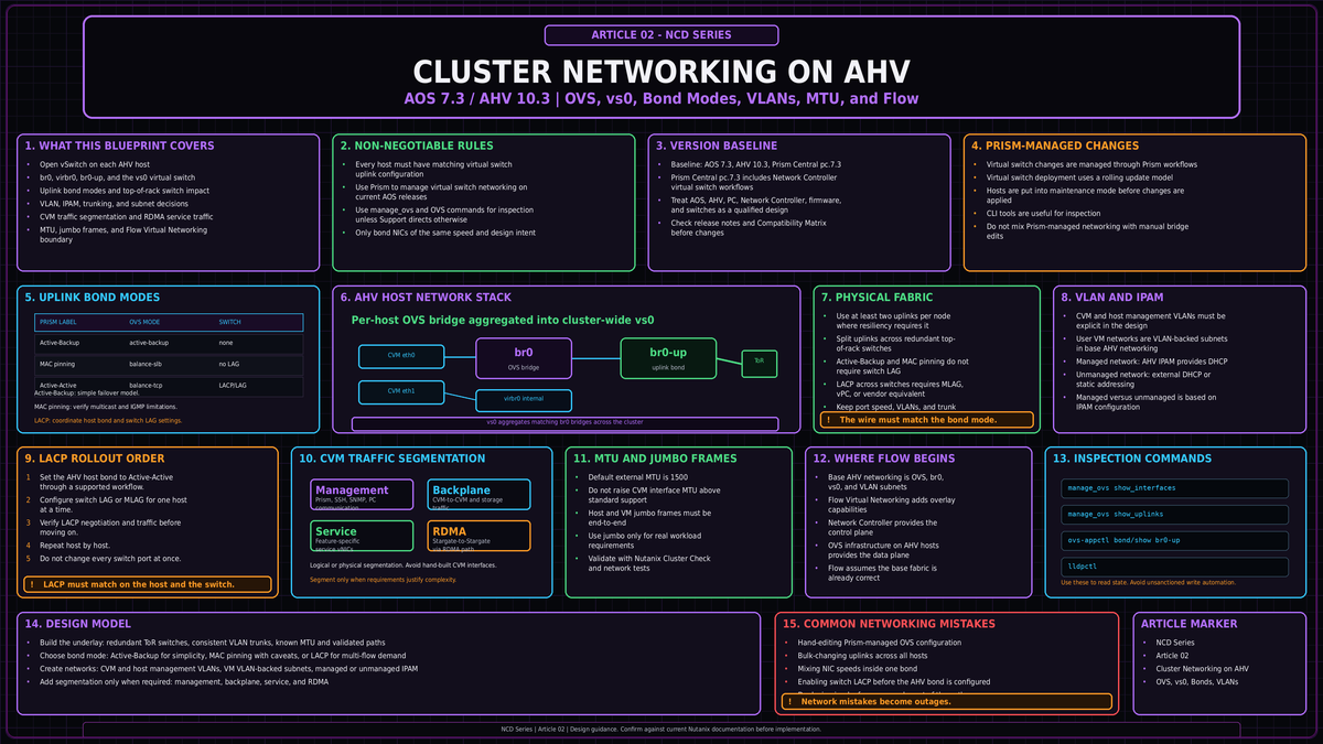
AHV networking looks deceptively simple in Prism. Behind the few clicks sits Open vSwitch on every host, a cluster wide virtual switch that demands identical configuration on each node, and a set of uplink decisions that determine throughput, failover behavior, and how much your top of rack switches need to know. Get the foundation wrong and you do not get a slow cluster. You get degraded nodes. This article covers cluster networking on AHV as you should design it on AOS 7.3 and AHV 10.3, from the bridge on a single host up to multicluster switching in Prism Central 7.3.
NCD-02Open vSwitch on every host
Every AHV host runs its own instance of Open vSwitch (OVS). OVS is an open source software switch that lives in the Linux kernel and behaves, by default, like a Layer 2 learning switch with a MAC address table. It is the single component that connects the Controller VM (CVM), the hypervisor itself, and every guest VM to each other and to the physical network.
The default install gives you two bridges per host. The first is br0, an OVS bridge that carries all storage, host, and VM traffic out to the wire. The second is virbr0, a native Linux bridge, not an OVS device, that exists purely to handle internal AOS traffic on the 192.168.5.0 network between the CVM and the local hypervisor. You never touch virbr0. It is plumbing.
The CVM presents two interfaces into this layout. The external interface, eth0, plugs into the OVS bridge and out through the uplinks. The internal interface, eth1, connects to virbr0 for CVM to hypervisor communication. In an unsegmented cluster, every kind of CVM traffic, management and storage replication alike, rides eth0. Keep that fact in mind. It is the entire reason network segmentation exists later in this article.
Inside br0, OVS uses ports to connect things. There are a handful of port types worth knowing:
| Port type | Purpose |
|---|---|
| Internal port | Shares the bridge name (br0) and provides the AHV host its own network access. |
| Tap port | Connects a guest VM virtual NIC to the bridge. One tap per vNIC. |
| VXLAN port | Used by the Acropolis IP address management (IPAM) function for managed networks. |
| Bonded port | Aggregates the host physical interfaces. The default bond is named br0-up. |
That bonded port is where uplink design happens, and it is where most cluster networking mistakes get made. Before we get there, understand how a per host bridge becomes a cluster wide construct.
From bridges to the virtual switch
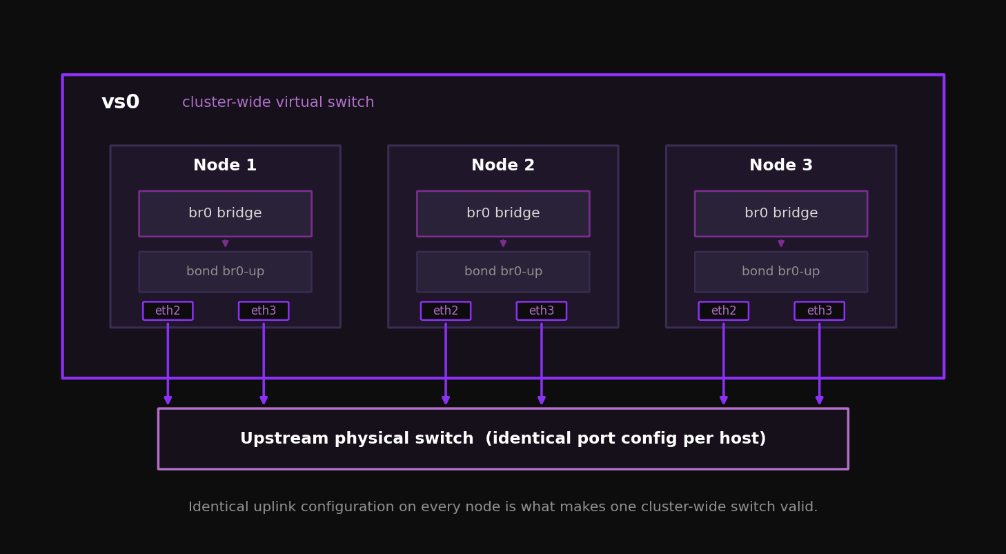
A bridge is local to one host. A cluster is not. Across all nodes, the individual br0 bridges are aggregated into a virtual switch. The default virtual switch is vs0. If a distributed virtual switch on vSphere is your mental reference, the comparison holds: vs0 is the cluster wide object, the per host br0 bridges are its members.
For that aggregation to work, one rule is non negotiable. Every host must have identical uplink configuration. Same physical port assignment, same bond name, same bond mode. The physical switch ports feeding each host must also be configured identically, presenting the same VLANs to every host uplink. Subnets are then added to the virtual switch and defined by a VLAN tag, which makes the subnet available on every host bridge. VMs connect to subnets through tap ports.
An inconsistent virtual switch is destructive. If bridges and bonds are not identical across every host, the virtual switch may not deploy or expand cleanly, NCC can raise alerts, and a bad manual correction can turn a healthy cluster into an outage. This is not a theoretical edge case. It is one of the easiest ways to break AHV networking by hand.
Manage the virtual switch from Prism, not the host
From AOS 5.19 onward, you manage bridges, bonds, and load balancing through the Prism virtual switch interface. When you change the virtual switch, Prism applies the change to every host for you. It walks the cluster node by node, places each host in maintenance mode, migrates VMs, makes the change, and brings the host back. You do not manually enter and exit maintenance mode, and you do not risk leaving hosts in mismatched states. On AOS 7.3, treat Prism as the exclusive method for network management.
The legacy CLI still exists. manage_ovs runs from the CVM and is useful for inspection. ovs-vsctl and ovs-appctl run on the AHV host and expose the raw OVS state. Use them to read, not to write. Command output and availability can vary by AOS and AHV release, so treat these examples as inspection references rather than automation templates.
Updating uplinks with manage_ovs ... update_uplinks deletes and recreates the bond with default configuration. If the cluster is using balance-slb or LACP, that command resets the bond to active and passive. Running allssh manage_ovs update_uplinks across every CVM at once can cause a cluster outage. Once you have configured the virtual switch in Prism, do not issue manage_ovs changes against it.
Inspection commands you will actually use:
nutanix@CVM$ manage_ovs show_interfaces
nutanix@CVM$ manage_ovs show_uplinks

Bridge: br0
Bond: br0-up
  bond_mode: active-backup
  interfaces: eth3 eth2
  lacp: off
  lacp-fallback: true
Multicluster virtual switches in Prism Central 7.3
Prism Central 7.3 adds the ability to create and manage a virtual switch that spans multiple clusters managed by the same Prism Central instance. A multicluster virtual switch is a software layer representing uplink ports connected to the same switching domain across hosts and clusters that share the same attributes. You map subnets to it, and those subnets span every cluster the virtual switch represents. You can then build VM vNICs on those subnets with reachability across clusters. Creating one requires Prism Central 7.3, Network Controller 6.0, AOS 7.3, and AHV 10.3. It also assumes the participating uplinks are connected to the same switching domain and share the same required attributes. In Prism Central 7.3, only Network Controller based VLAN subnets or a VPC can be associated to a multicluster virtual switch; AHV VLAN Basic subnets and individual overlay subnets are not mapped to it. This is the scope where a managed service operator running several clusters under one Prism Central starts to treat networking as a fleet wide object rather than a per cluster one.
Uplink design: bond modes and NIC teaming
The bond inside br0 aggregates your physical interfaces. OVS supports three load balancing modes, and Prism exposes them under its own labels. Choosing among them is the single most consequential networking decision in the cluster, because it sets your throughput ceiling and dictates how much configuration the top of rack switches need.
| Prism label | OVS mode | Switch config | Host throughput | Single VM throughput |
|---|---|---|---|---|
| Active-Backup | active-backup | None | One link (for example 10 Gb) | One link |
| Active-Active with MAC pinning | balance-slb | None | Sum of links (for example 20 Gb) | One link |
| Active-Active | balance-tcp with LACP | LAG and LACP required | Sum of links | Can exceed one link |
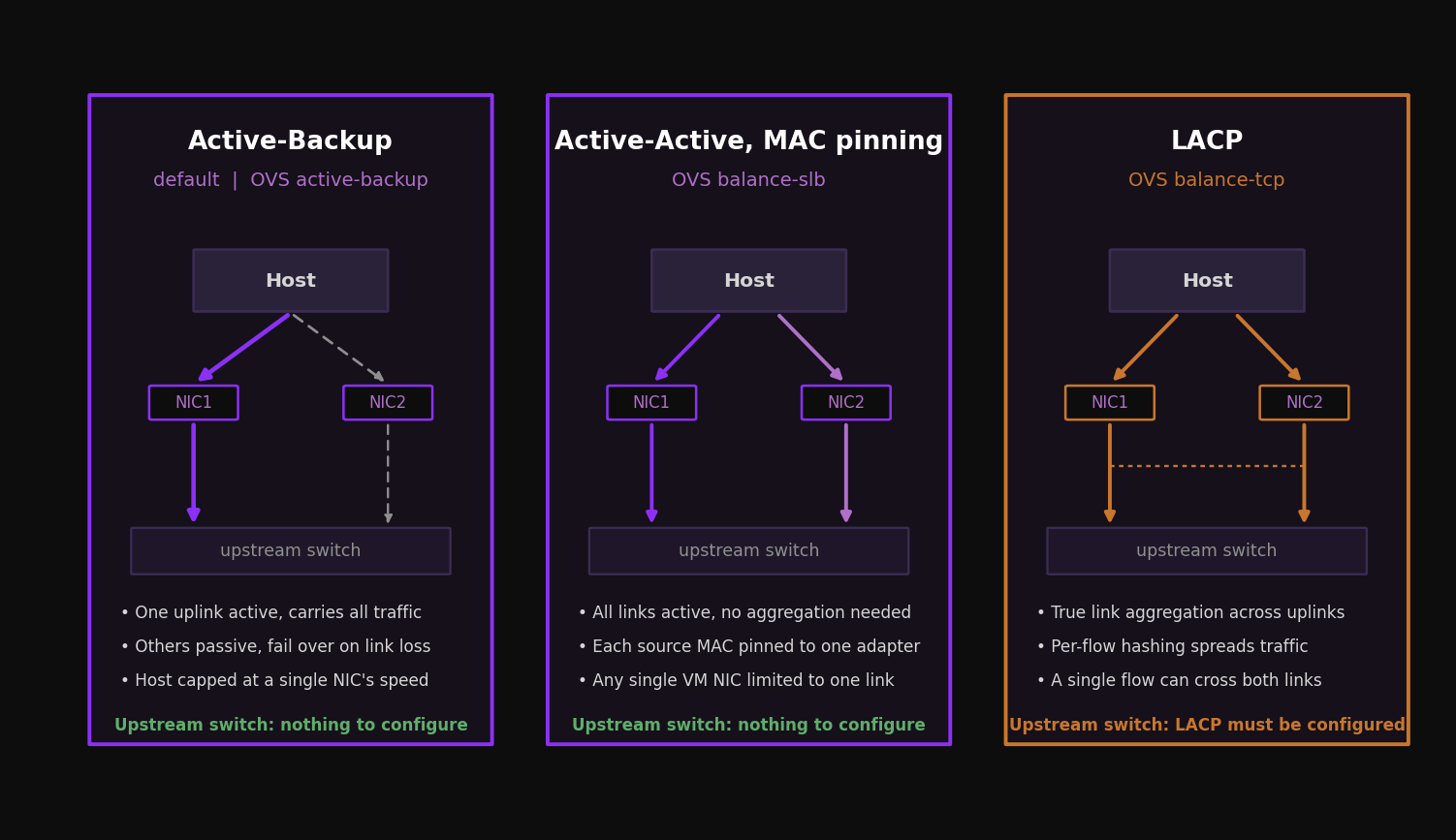
Active-Backup
This is the default after installation and the simplest to run. One uplink is active and carries all traffic. The rest sit passive and take over only when the active link fails. There is no upstream switch configuration to coordinate, which is exactly why it is the default. The cost is throughput: the whole host is capped at the speed of a single NIC. For many clusters this is fine. If your nodes have a pair of 10 Gb interfaces and your aggregate host traffic stays under 10 Gb, Active-Backup gives you clean, predictable failover with nothing to misconfigure on the network side.
Active-Active with MAC pinning
This is OVS balance-slb. It uses all links without requiring any link aggregation on the switch. The bond pins each source MAC address to one adapter at a time, and a hashing algorithm spreads multiple source MACs across the available members. OVS periodically rebalances based on measured load per interface. The result is that a host with two 10 Gb interfaces can push up to roughly 20 Gb of aggregate throughput, while any single VM NIC is still limited to one link, because that NIC maps to one adapter.
The reason to reach for MAC pinning is exactly the scenario in the table: many small VMs on a host where you want aggregate bandwidth without touching the switch. There is one caveat you must respect.
With balance-slb, the virtual switch forwards inbound multicast on only one active adapter and discards multicast arriving on the others. Physical switches running IGMP snooping may send multicast to an adapter the bond is not treating as active, and the traffic gets dropped. Disable IGMP snooping, or configure static IGMP groups, on every switch port connected to Nutanix nodes using MAC pinning. Nutanix does not recommend balance-slb for multicast heavy traffic.
Active-Active (LACP and balance-tcp)
This is OVS balance-tcp with LACP. It is the only mode where a single VM with multiple TCP streams can use more than one link of bandwidth, because traffic is balanced per Layer 4 flow using source and destination IP plus source and destination ports. That hashing maps directly to the Cisco EtherChannel method of source and destination port load balancing. A node with two 10 Gb adapters can deliver aggregate throughput above one link to a single demanding VM when that VM generates multiple Layer 4 flows. A single flow is still bounded by the selected physical link.
The price is upstream configuration. LACP and balance-tcp require a link aggregation group on the top of rack switch for every node. Because of that dependency, moving a cable to an incorrectly configured switch port can drop connectivity. The order of operations matters, and Prism makes it survivable:
- 1Change the host side first. Set the cluster virtual switch to Active-Active with LACP, keeping LACP fallback enabled. Prism performs a rolling change, putting each host in maintenance mode in turn. With fallback enabled and the switch side not yet configured, the bond falls back to active and passive, so the host stays reachable.
- 2Configure the switch side per host. Place one host in maintenance mode, enable LAG and LACP on its top of rack ports, confirm the link aggregates, then move to the next host. Never configure all switch ports at once.
- 3Verify. Confirm bond state and LACP negotiation before moving on.
nutanix@CVM$ ssh root@192.168.5.1 "ovs-appctl bond/show br0-up"

bond_mode: balance-tcp
lacp_status: negotiated
member eth2: enabled
member eth3: enabled active member
Two physical rules apply across all three modes. Only put NICs of the same speed in the same bond. Do not mix a 10 Gb and a 1 Gb interface in one bond; if a node ships with both, the common guidance is to use the 10 Gb NICs and leave the 1 Gb NICs unplugged. And keep the bond named br0-up rather than renaming it, so the configuration reads consistently across the fleet.
The physical fabric beneath the bond
Bond mode decisions only pay off if the physical fabric supports them. Design the wire with the same redundancy assumptions AOS makes about nodes.
Give every node at least two uplinks, split across two top of rack switches, so the loss of one switch does not isolate a host. With Active-Backup or MAC pinning, two independent switches work without any link aggregation between them. With Active-Active, you need the two switches to present a single logical aggregation to the host, which means a multichassis link aggregation arrangement (MLAG, vPC, or the equivalent for your vendor) so the LAG can span both switches and survive one failing.
On port speed, 10 Gb is the practical floor for production AHV, and 25 Gb is increasingly the sensible default for new builds, particularly where you expect heavy storage replication or you plan to consolidate management, backplane, and VM traffic onto the same uplinks. Storage traffic between CVMs is east to west and latency sensitive, so a low oversubscription leaf and spine fabric serves a Nutanix cluster better than a deep, heavily oversubscribed tree. When you need to troubleshoot a miscabled node without walking the data center, lldpctl on the AHV host reads Link Layer Discovery Protocol from the directly connected switch and tells you which port a NIC actually lands on.
VLANs and the untagged host design
AHV supports VLANs for the CVM, the AHV host, and user VMs. The design choice that trips people up is what to do with the CVM and host themselves.
By default, the CVM public interface is assigned to VLAN 0, meaning its traffic is untagged. The clean approach is to make the CVM and host VLAN the untagged VLAN on the trunk feeding each host. The switch ports are trunks carrying every VLAN the cluster needs, with the management VLAN left untagged so CVM and host traffic flows without a tag while user VM VLANs arrive tagged. This keeps CVM and host on the same VLAN, which is the supported baseline, and still lets you separate user VM traffic into as many tagged VLANs as you need. If you instead configure the host ports as access ports for a single VLAN, you lose the ability to trunk multiple VM VLANs to that host.
For user VMs, each Acropolis network is bound to a single VLAN. Trunking multiple VLANs onto one network is not supported at the network object level. Where a guest genuinely needs to see multiple tagged VLANs on one vNIC, for example a virtual firewall or router, you create the vNIC in trunked mode through the aCLI, which allows multiple tagged VLANs on a single virtual NIC. You can also convert an existing vNIC from access mode, carrying one untagged VLAN, to trunked mode.
IPAM: managed versus unmanaged networks
When you create a network for user VMs, you choose managed or unmanaged, and that choice is permanent. You cannot convert one to the other after creation, so decide deliberately.
An unmanaged network is a straight Layer 2 connection. The VM lands on its chosen VLAN and gets its address from whatever external DHCP server or static assignment your environment already uses. AHV stays out of address management entirely.
A managed network turns on the built in Acropolis IPAM function. AHV runs an internal DHCP server and hands out addresses from configurable pools you define on the network, along with gateway, subnet mask, and DNS settings. Acropolis intercepts outbound DHCP requests from guest VMs using VXLAN and OpenFlow rules inside OVS, so the DHCP exchange between the VM and the CVM never reaches the physical network. An address is leased from the pool when a managed vNIC is created and released back when the vNIC or VM is deleted.
Before you enable IPAM on a VLAN, reserve that address range with your network team so the Acropolis pool cannot overlap with anything handed out elsewhere. IPAM is convenient precisely because it removes an external dependency, but a pool that collides with an existing DHCP scope creates duplicate addresses that are tedious to chase down.
Creating networks from the CVM is straightforward, and the same command covers both kinds. An unmanaged network needs only a name and VLAN. A managed network adds an IP configuration:
<acropolis> net.create PROD-WEB vlan=84 virtual_switch=vs0
<acropolis> net.create PROD-DB vlan=85 virtual_switch=vs0 ip_config=10.0.85.254/24
Network segmentation
Recall that in an unsegmented cluster, all CVM traffic shares eth0. Network segmentation splits that traffic apart for security, resilience, or performance. There are four kinds of CVM traffic to reason about:
| Traffic type | What it is |
|---|---|
| Management | Prism, SSH, remote logging, SNMP, Prism Element to Prism Central, anything needing the default gateway. In current AOS this is defined as any traffic not on the backplane, so it also covers user VM to CVM communication. Rides eth0. |
| Backplane | CVM to CVM cluster service traffic and storage replication, plus host to host and host to CVM traffic. The bulk of intra cluster storage I/O. |
| Service | A user chosen AOS feature, for example Nutanix Volumes, confined to its own vNIC and dedicated virtual network. |
| RDMA | A special service type limited to Stargate to Stargate communication. Rather than a vNIC, a physical NIC is passed through from the hypervisor to the CVM for direct remote memory access. |
The separation works by giving each isolated traffic type its own interface on the CVM. An eth2 backplane interface is created on each CVM during the upgrade to an AOS release that supports segmentation, and it sits unused, without an IP, until you enable backplane segmentation. Service interfaces are created at runtime when you trigger the operation.
Logical versus physical separation
Backplane traffic can be isolated two ways. Logical segmentation puts the backplane on a dedicated, nonroutable VLAN that still shares the same physical adapters on br0. It separates the traffic classes without new hardware. Physical segmentation gives the backplane its own physical NICs and virtual network, delivering true isolation at the cost of additional adapters and switch ports. The optional backplane LAN creates a dedicated interface in a separate VLAN on all CVMs for storage replication, and you should enable it only when you have a real requirement to separate management traffic such as Prism from storage replication. Do not segment by default. Each segment you add is configuration you have to keep identical across every node, and that surface area is where degraded states originate.
Service specific segmentation, isolating something like Volumes onto its own vNIC and dedicated physical NICs, is supported on AHV and ESXi. RDMA segmentation passes a physical NIC through to the CVM so Stargate can use it directly. Both buy you isolation and bandwidth for a specific service, and both add operational complexity. Reach for them when a workload or a security boundary demands it, not as a starting position.
Segmentation is not supported if the CVMs already have a manually created eth2 interface, if eth2 has been given an IP by hand, or if the cluster already runs multiple virtual switches or bridges to isolate CVM traffic. Let AOS own the segmentation interfaces. Hand crafted CVM network changes are exactly the kind of unsupported alteration that can cost you user VMs.
MTU and jumbo frames
AHV uses the standard 1,500 byte Ethernet MTU for all external communication by default, and that default is the right answer far more often than engineers expect. Nutanix does not support raising the MTU on a CVM network interface above the standard value. The 1,500 byte frame delivers excellent performance and stability for storage traffic, and the throughput gain from moving CVM traffic to 9,000 byte frames is generally not significant.
You can enable jumbo frames (9,000 bytes) on the physical interfaces of AHV hosts and on user VMs where an application genuinely needs them. There are two cases where it is worth the effort:
- High performance iSCSI workloads using Nutanix Volumes (ABS), where larger frames reduce overhead on a busy storage path.
- Flow Virtual Networking, where Geneve encapsulation adds 58 bytes per frame. Here Nutanix recommends raising the MTU to 9,000 on the
vs0virtual switch and on the physical fabric, with a supported range of 1,600 to 9,000 bytes.
The Flow case has a sharp edge. The system advertises a 1,442 byte MTU to guest VMs over DHCP to leave room for the Geneve overhead, but Windows guests ignore the MTU value in a DHCP response. If you run Flow Virtual Networking with Windows VMs, you must enable jumbo frame support on the physical network and on vs0 so the larger encapsulated frames are not fragmented.
If you enable jumbo frames, enable them end to end. Every device in the path, physical switches, hosts, and guests, must agree on the MTU, and the switches must account for VLAN tags and any VXLAN or Geneve overhead on top of the 9,000 byte payload. A partial deployment produces fragmentation, poor performance, or dropped connectivity. Plan it deliberately and validate with the NCC MTU checks.
Where AHV networking ends and Flow begins
Everything to this point describes the base networking layer: OVS bridges, the vs0 virtual switch, uplink bonds, VLAN backed subnets, and segmentation. That layer is enough to build and run a production cluster.
Flow Virtual Networking sits on top of it as a native extension, not a separate add on. When you enable it, an OVN managed OVS bridge called brAtlas is created on every host. Flow constructs and security rules are realized as OpenFlow rules in brAtlas: VPCs become logical routers, subnets become logical switches, and policies become access control lists. Overlay traffic uses Geneve encapsulation, with all hosts communicating over UDP port 6081, and by default that overlay traffic still traverses vs0 and br0 using the host IP as the tunnel endpoint. Overlay networks can span multiple AHV clusters managed by the same Prism Central and Network Controller.
The takeaway for cluster design is the boundary. Your uplink bonds, VLAN scheme, segmentation, and MTU decisions are the foundation Flow builds on. Get them right first. VPCs, overlay subnets, and distributed firewalling are a later design conversation that assumes this layer is already correct and consistent across every node. Those topics belong to their own articles in this series.
- Every AHV host runs OVS with a default
br0uplink bridge and an internalvirbr0bridge; the per host bridges aggregate into the cluster widevs0virtual switch. - The virtual switch is only valid when uplink configuration is identical on every host. Inconsistent bridges and bonds can keep the virtual switch from deploying or expanding cleanly, and a bad manual correction can turn a healthy cluster into an outage.
- Manage networking through Prism on AOS 7.3. Use
manage_ovs,ovs-vsctl, andovs-appctlto read state, never to change a Prism managed virtual switch. - Choose the bond mode for the workload: Active-Backup for simple failover, Active-Active with MAC pinning for host aggregate bandwidth without switch config, Active-Active with LACP when a single VM needs more than one link. MAC pinning carries an IGMP and multicast caveat; LACP requires per node LAG on the top of rack.
- Keep the CVM and host on the untagged management VLAN of the host facing trunk and carry user VM networks as tagged VLANs; use only same speed NICs in a bond.
- Decide managed versus unmanaged at network creation; the choice is permanent. Managed networks run the built in Acropolis DHCP and need a reserved address range.
- Segment management, backplane, service, and RDMA traffic only when there is a real requirement; let AOS own the
eth2and service interfaces. - Default to a 1,500 byte MTU. Enable jumbo frames end to end only for ABS iSCSI or Flow Virtual Networking, and remember Windows guests ignore the DHCP advertised MTU under Geneve.
- Flow Virtual Networking extends this base layer through the
brAtlasbridge and Geneve overlays. Build the foundation correctly before you layer it on.